# W oknie ''<IS_TS id=DataEditorTable/>'' określić wymagane dane dla elementów sieci:
# W oknie ''<IS_TS id=DataEditorTable/>'' określić wymagane dane dla elementów sieci:
#* ''<IS_TS id=strPoleTerenProj/>''. The ''<IS_TS id=strAUTOModeName/>'' mode sets the following parameters:
#* ''<IS_TS id=strPoleTerenProj/>''. W trybie ''<IS_TS id=strAUTOModeName/>'' ustawiane są następujące parametry:
#** for the ''<IS_TS id=iNamePrfStudzienkaWod/>'' / ''<IS_TS id=iNamePrfSkrzyzowanieSieciWod/>'' within the ''<IS_TS id=ScopeNet_terrain/>'' ''<IS_TS id=stringProjektowane/>'' area, the value of ''<IS_TS id=strPoleTerenProj/>'' is taken from the model of ''<IS_TS id=ScopeNet_terrain/>'',
#** dla elementu ''<IS_TS id=iNamePrfStudzienkaWod/>'' / ''<IS_TS id=iNamePrfSkrzyzowanieSieciWod/>'' w obszarze ''Terenu projektowanego'', ''<IS_TS id=strPoleTerenProj/>'' jest pobierana z ''Modelu terenu'',
#** for the ''<IS_TS id=iNamePrfStudzienkaWod/>'' / ''<IS_TS id=iNamePrfSkrzyzowanieSieciWod/>'' outside the ''<IS_TS id=ScopeNet_terrain/>'' ''<IS_TS id=stringProjektowane/>'' area, the ''<IS_TS id=DomyslnaRzednaTerenu/>'' for the ''<IS_TS id=iNamePrfMapaGeod />'' is propagated by default;
#** dla elementu ''<IS_TS id=iNamePrfStudzienkaWod/>'' / ''<IS_TS id=iNamePrfSkrzyzowanieSieciWod/>'' spoza obszaru ''Terenu projektowanego'', ''<IS_TS id=DomyslnaRzednaTerenu/>'' propagowana jest z ''Mapy'';
#* ''<IS_TS id=strPoleTerenIst/>''. The ''<IS_TS id=strAUTOModeName/>'' mode sets the following parameters:
#* ''<IS_TS id=strPoleTerenIst/>''. The ''<IS_TS id=strAUTOModeName/>'' mode sets the following parameters:
#** for the ''<IS_TS id=iNamePrfStudzienkaWod/>'' / ''<IS_TS id=iNamePrfSkrzyzowanieSieciWod/>'' within the ''<IS_TS id=ScopeNet_terrain/>'' ''<IS_TS id=stringIstniejace/>'' area, the value of ''<IS_TS id=strPoleTerenIst/>'' is taken from the model of ''<IS_TS id=ScopeNet_terrain/>'',
#** for the ''<IS_TS id=iNamePrfStudzienkaWod/>'' / ''<IS_TS id=iNamePrfSkrzyzowanieSieciWod/>'' within the ''<IS_TS id=ScopeNet_terrain/>'' ''<IS_TS id=stringIstniejace/>'' area, the value of ''<IS_TS id=strPoleTerenIst/>'' is taken from the model of ''<IS_TS id=ScopeNet_terrain/>'',
Linia 98:
Linia 98:
#* ''<IS_TS id=strpnPrfWejscieDoBudWod/>'' - for the ''<IS_TS id=iNamePrfWejscieDoBudWod/>'',
#* ''<IS_TS id=strpnPrfWejscieDoBudWod/>'' - for the ''<IS_TS id=iNamePrfWejscieDoBudWod/>'',
#* ''<IS_TS id=strLblKsztaltCaption/>'' and ''Dimensions''- for the ''<IS_TS id=iNamePrfStudzienkaWod/>''.<br/>[[File:Designing water supply network Elements data.png|900 px|left|thumb|11. Editing data of network elements.]]<br clear="all"/>
#* ''<IS_TS id=strLblKsztaltCaption/>'' and ''Dimensions''- for the ''<IS_TS id=iNamePrfStudzienkaWod/>''.<br/>[[File:Designing water supply network Elements data.png|900 px|left|thumb|11. Editing data of network elements.]]<br clear="all"/>
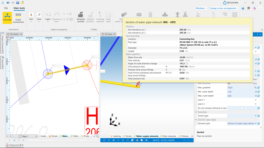
# (Optionally) Modify network elements data if data differs from the default settings;<br/>[[File:Designing water supply network WP section.png|900 px|left|thumb|12. <IS_TS id=DataEditorTable/>.]]<br clear="all"/>
# (Opcjonalnie) Modify network elements data if data differs from the default settings;<br/>[[File:Designing water supply network WP section.png|900 px|left|thumb|12. <IS_TS id=DataEditorTable/>.]]<br clear="all"/>
# (Optionally) Modify ''<IS_TS id=Wykopy/>'' data if data differs from the default settings;
# (Opcjonalnie) Zmodyfikować ''<IS_TS id=Wykopy/>'' data if data differs from the default settings;
Projekt zawiera kompletne domyślne dane skonfigurowane w pliku szablonu.
Kroki do wykonania
Otwarcie nowego pliku projektu
Uruchomić NetSystem 5.5. Uwaga: Interfejs programu i podstawowe funkcje są bardzo podobne do tych używanych w InstalSystem 5.5. Dlatego poniżej znajdują się linki do artykułów związanych z InstalSystem 5.5, które mają zastosowanie również w NetSystem 5.5.
Wybrać wymagany plik szablonu (opcjonalnie). Więcej informacji na ten temat:Pliki szablonów.
Edycja katalogów i danych ogólnych projektu
Uzupełnić dane domyślne w oknie Dane ogólne:
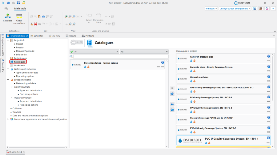
Katalogi produktów – wybrać i przenieść niezbędne katalogi do tabeli Katalogi w projekcie:. W celu przyspieszenia wyboru można wykorzystać filtry katalogów. Więcej informacji na ten temat:Użycie katalogów i danych katalogowych w projekcie. 1. Katalogi produktów.
Arkusze robocze / Arkusze map:
(Opcjonalnie) Zmodyfikować wartość Domyślna rzędna terenu,
Dodać nowe Arkusze map, jeśli jest taka konieczność;
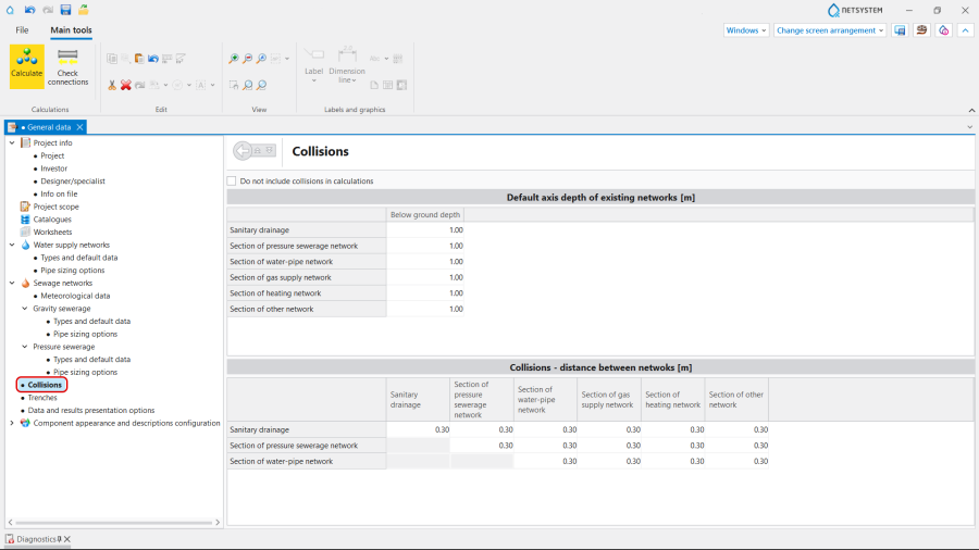
Kolizje - zweryfikować i w razie potrzeby dostosować ustawienia kolidujących sieci w odniesieniu do Domyślne zagłębienie sieci istniejących i Kolizje - odległości mijania sieci. 4. Kolizje.
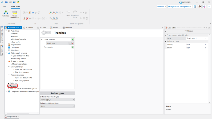
(Opcjonalnie) Wykopy - dodać Domyślny typ wykopu liniowego i Domyślny typ wykopu punktowego. 5. Wykopy.
Import mapy geodezyjnej
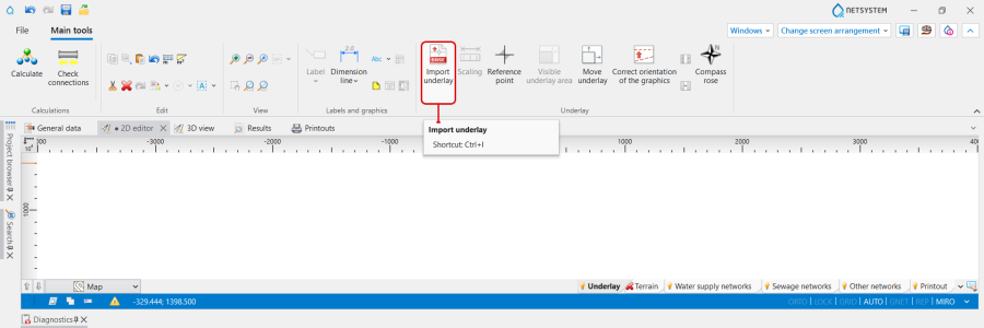
Użyć funkcji Importuj podkład, aby zaimportować mapę geodezyjną w kompatybilnych formatach plików podkładów:
DWG
DXF
PDF
BMP
PNG
JPG
GIF
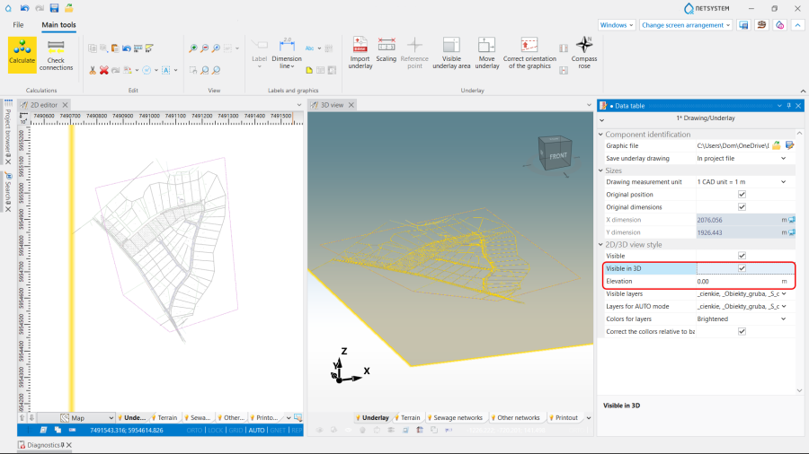
ASC 6. Importuj podkład. Dla Rysunku/Podkładu w formacie DWG można w oknie Tabela danych włączyć ustawienie Widoczny w 3D oraz może zostać określona Rzędna, na której mapa ma być widoczna. 7. Widoczny w 3D. Więcej informacji na ten temat:Import plików podkładów.
Modelowanie terenu
Powiązane funkcje są dostępne, gdy aktywny jest zakres edycji Teren:
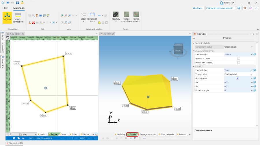
8. Modelowanie terenu.
Modelowanie terenu:
Wstawić element TerenProjektowany lub
Wstawić element TerenIstniejący;
Punkt terenu:
Wstawić element Punkt terenu - Projektowany lub
Wstawić element Punkt terenu - Istniejący;
Jezdnia:
Wstawić element Jezdnia - Projektowana lub
Wstawić element Jezdnia - Istniejąca. 9. Teren Projektowany.
Edycja sieci
Wykonywać operacje wstawiania i edycji grafiki w trybie AUTO.
Wybrać zakres edycji Sieci wodociągowe.
Wstawić podstawowe elementy:
Studzienka wodomierzowa,
Węzeł sieci wodociągowej,
Hydrant,
Wejście sieci wod. do budynku;
Połączyć elementy używając Odcinek sieci wodociągowej. Uwaga: Alternatywnie można najpierw narysować sieć, a następnie rozmieścić podstawowe elementy.
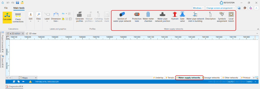
Wstawić element Zasuwa. 10. Sieci wodociągowe elementy.
Edycja danych elementów sieci
W oknie Tabela danych określić wymagane dane dla elementów sieci:
Rzędna terenu projektowanego. W trybie AUTO ustawiane są następujące parametry:
dla elementu Studzienka wodomierzowa / Węzeł sieci wodociągowej w obszarze Terenu projektowanego, Rzędna terenu projektowanego jest pobierana z Modelu terenu,
dla elementu Studzienka wodomierzowa / Węzeł sieci wodociągowej spoza obszaru Terenu projektowanego, Domyślna rzędna terenu propagowana jest z Mapy;
Rzędna terenu istniejącego. The AUTO mode sets the following parameters:
for the Studzienka wodomierzowa / Węzeł sieci wodociągowej within the TerenIstniejące area, the value of Rzędna terenu istniejącego is taken from the model of Teren,
for the Studzienka wodomierzowa / Węzeł sieci wodociągowej outside the TerenIstniejące area, the Domyślna rzędna terenu for this element is taken from the Rzędna terenu projektowanego;
Rzędna wejścia do budynku - for the Wejście sieci wod. do budynku,
Funkcja - for the Węzeł sieci wodociągowej,
Wypływ w punkcie, Wym. ciśn. and Ciśn. max. - for the Wejście sieci wod. do budynku and Hydrant,
Rodzaj wejścia do bud - for the Wejście sieci wod. do budynku,
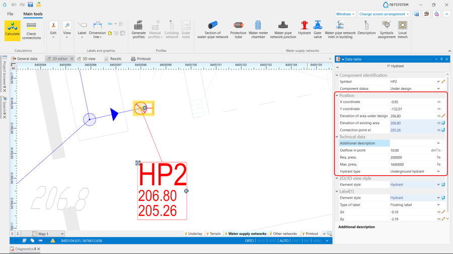
Kształt and Dimensions- for the Studzienka wodomierzowa. 11. Editing data of network elements.
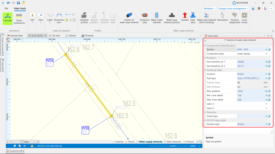
(Opcjonalnie) Modify network elements data if data differs from the default settings; 12. Tabela danych.
(Opcjonalnie) Zmodyfikować Wykopy data if data differs from the default settings;
(Opcjonalnie) Wstawić Rura ochronna;
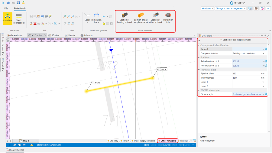
(Opcjonalnie) tworzyć Pozostałe sieci working scope. Insert uncalculated conflicting Inne sieci, defining the Stan elementu, Położenie and Dane techniczne. 13. Pozostałe sieci.
Network structure correctness verification
Verify correctness of the network structure using Sprawdź połączenia function (shortcut: Shift + F2);
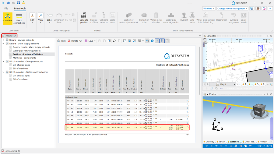
Verify the results in the Wyniki tables; 15. Wyniki tables.
Every item of the network presented in the Wyniki tables can be found in active windows by using icon.
The data of each element can be verified directly in the drawings by means of component labeling and hints containing tables with basic parameters. 16. Visual verification in the Widok 3D window.
Preparing drawings and results for printing / exporting
To have the results for Sieci wodociągowe elements included in the printout of a drawing, appropriate labels must be inserted. Więcej informacji na ten temat:Preparation of drawings for export / printing.








 in the Obliczenia section of the toolbar;

 icon.
icon.