Kanalizacja grawitacyjna - wentylacja obejściowa
Przejdź do nawigacji
Przejdź do wyszukiwania
| Produkt | InstalSystem 5 |
| Typ artykułu | PRZYKŁADOWY PROJEKT |
| Ostatnia aktualizacja | 2023-08-21 |
Opis projektu
Załączone projekty przedstawiają przykładowe rozwiązania instalacji kanalizacyjnej z wentylacją obejściową.
Schematy A-D są odpowiednie do zastosowania w budynkach posiadających od 3 do 5 pięter (o łącznej wysokości mniejszej bądź równej 12m).
Schemat E - dla budynków posiadających więcej, niż 5 pięter (o łącznej wysokości większej, niż 12m).
Pliki do pobrania i informacje o projekcie
Schemat A
- Bezpośrednio równoległa wentylacja/Direct parallel ventilation: pion wentylacyjny jest podłączony z pionem kanalizacyjnymvent na dole w pobliżu podnóża pionu i u góry rury wywiewnej;
- Generuj łączniki wentylacyjne can be made or not depending on the project features.
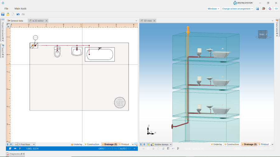
1. Schemat A.
Bypass ventilation Schema A, isproj

Schemat B
- Indirect parallel ventilation: vent stack is a separate one, and is connected to the branches on each floor. Horizontal ventilation pipes are to be drawn manually, correcting the elevation where necessary;
- Zawór odpowietrzająco- napowietrzający is used as an Elem. zakończenia pionu for both stacks (Kanalizacja sanitarna and Wentylacja kanalizacji).
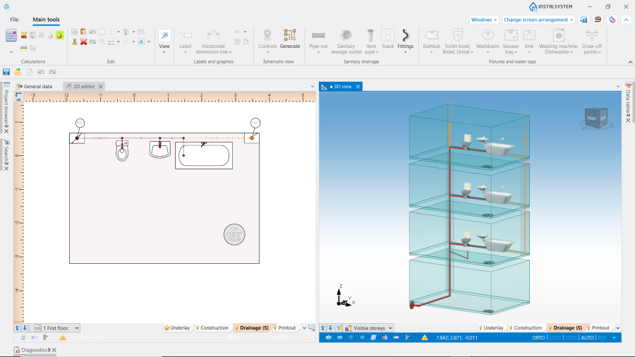
2. Schema B.
Bypass ventilation Schemat B, isproj

Schemat С
- Direct parallel ventilation: vent stack is connected to the sewage stack at the bottom near the stack foot and at the top to the vent pipe;
- Generuj łączniki wentylacyjne are made;
- Connection to the vent stack from each fixture on the first floor and from each sewage branch on the floors above.
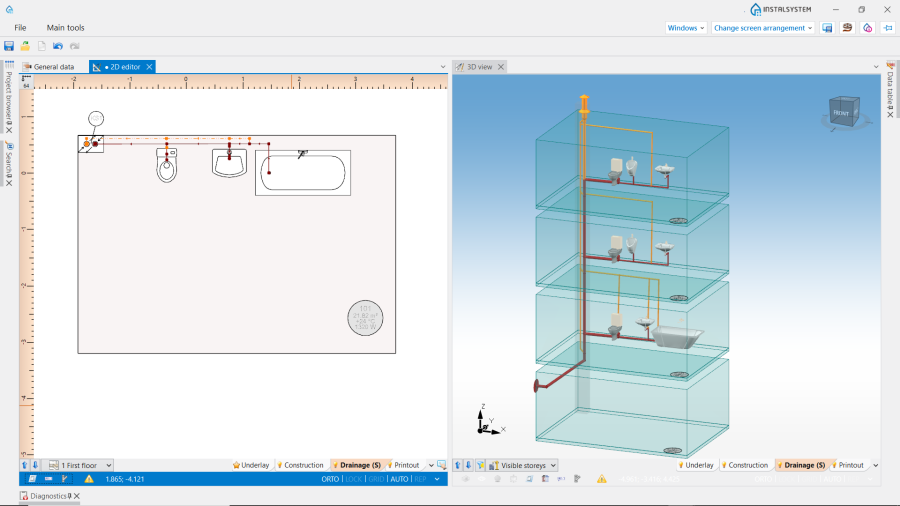
3. Schema C.
Bypass ventilation Schemat C, isproj

Schemat D
- Zawór odpowietrzająco- napowietrzający is used on the first floor for the most distant fixture;
- Działka wentylacji kanalizacji are connected to the sewage stack on the floors above.
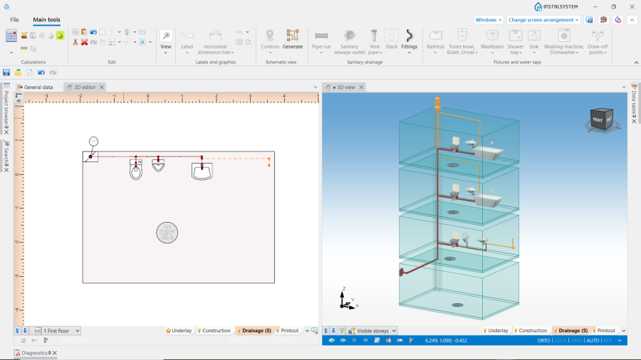
4. Schema D.
Bypass ventilation Schemat D, isproj

Schemat E
- In high buildings the fixtures on the lowest floors should be connected to the additional sewage pipe in the stack;
- The additional sewage pipe should be connected to the sewage collector at least 2 m from the base of the stack;
- Generuj łączniki wentylacyjne is declared as well;
- The connection of the additional stack to the main stack is made by the means of a "vent loop".
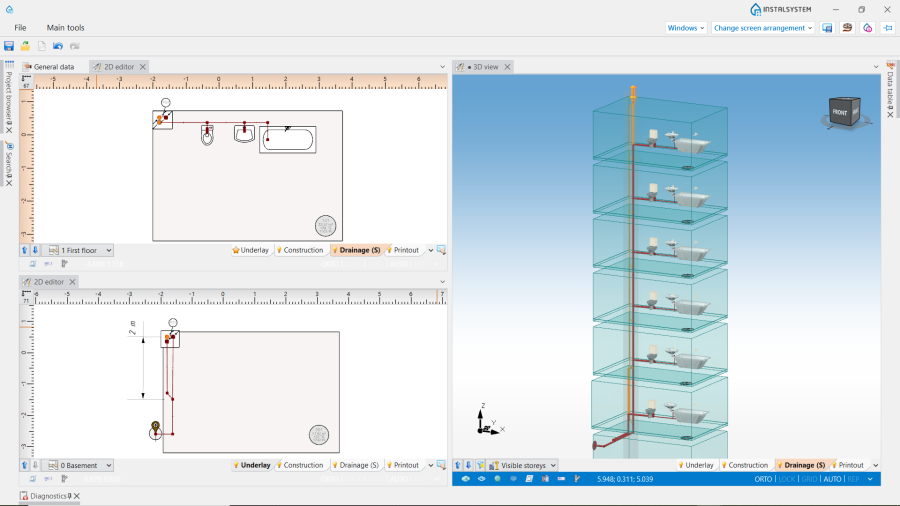
5. Schemat E.
Bypass ventilation Schema E, isproj
