|p3 =<!--gdy jest kolejny produkt handlowy, zamienić na->"produkt_handlowy3="-->
|p3 =<!--gdy jest kolejny produkt handlowy, zamienić na->"produkt_handlowy3="-->
|p4 =<!--gdy jest kolejny produkt handlowy, zamienić na->"produkt_handlowy3="-->
|p4 =<!--gdy jest kolejny produkt handlowy, zamienić na->"produkt_handlowy3="-->
|category1 =InstalSystem 5#Designing lessons
|category1 =InstalSystem 5#Lekcje projektowania
|category_name1 =DESIGNING LESSON
|category_name1 =LEKCJA PROJEKTOWANIA
|c2 =<!--Jest kategoria -> zamienić na: "category2=" i uzupełnić link do sekcji kategorii na stronie głównej produktu-->
|c2 =<!--Jest kategoria -> zamienić na: "category2=" i uzupełnić link do sekcji kategorii na stronie głównej produktu-->
|category_name2 =<!--podać nazwę kategorii "ZASTOSOWANIE"/"FUNKCJONALNOŚĆ"/...-->
|category_name2 =<!--podać nazwę kategorii "ZASTOSOWANIE"/"FUNKCJONALNOŚĆ"/...-->
Linia 17:
Linia 17:
==Scope of lesson==
==Zakres lekcji==
The article presents how to design external ''<IS_TS id=PH_NS5_SAN_T/>''.
Artykuł prezentuje jak w programie ''NetSystem 5'' projektować zewnętrzne ''<IS_TS id=PH_NS5_SAN_T/>''.
==Modules and program configuration==
==Potrzebne moduły i konfiguracja programów==
* '''NetSystem 5''' with the module:
* '''NetSystem 5''' z modułem:
**'''<IS_TS id=PH_NS5_SAN_T/>'''.
**'''<IS_TS id=PH_NS5_SAN_T/>'''.
==Project file==
==Plik projektu==
The project file used in this lesson: [[Water supply network (example for the lesson)]].
The project file used in this lesson: [[Water supply network (example for the lesson)]].
==Initial state==
==Stan początkowy==
The project contains complete default data configured in the template file.
The project contains complete default data configured in the template file.
==Kroki do wykonania==
==Steps to perform==
===Otwarcie nowego pliku projektu===
# Uruchomić '''NetSystem 5.5'''. <br/>'''''Uwaga:''''' The program interface and basic functions are very similar to those used in InstalSystem 5.5. Therefore, below are links to articles related to InstalSystem 5.5 that are also applicable to NetSystem 5.5.
===Opening the project file===
# Launch '''NetSystem 5.5'''. <br/>'''''Note:''''' The program interface and basic functions are very similar to those used in InstalSystem 5.5. Therefore, below are links to articles related to InstalSystem 5.5 that are also applicable to NetSystem 5.5.
# Open a new project.<br/>{{Info}} [[Project and application management]].
# Open a new project.<br/>{{Info}} [[Project and application management]].
Fill in the default data in the ''<IS_TS id=btProjectOptions/>'' window:
Fill in the default data in the ''<IS_TS id=btProjectOptions/>'' window:
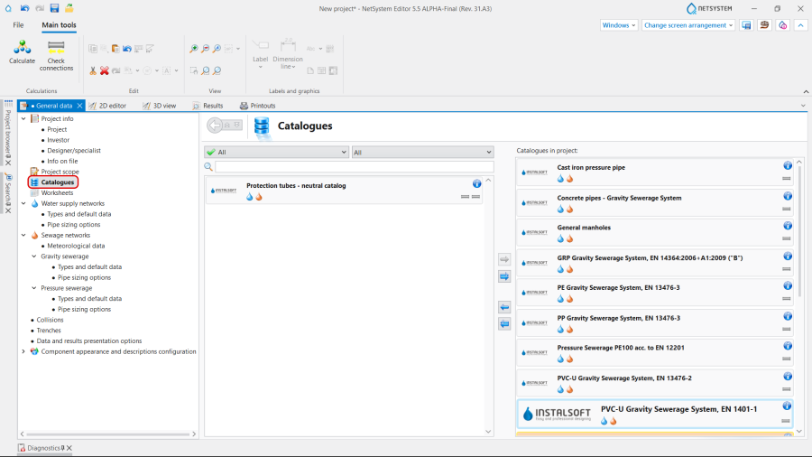
# ''<IS_TS id=rsObslugaKatalogowHint/>'' – select and move necessary catalogues to the ''<IS_TS id=strDstLabelCaption/>'' table. To speed up the selection, the filters can be used. {{Info}} [[Using catalogues and catalogues data in the project]].<br/>[[File:Designing water supply network Catalogues.png |900 px|left|thumb|1. <IS_TS id=rsObslugaKatalogowHint/>.]]<br clear="all"/>
# ''<IS_TS id=rsObslugaKatalogowHint/>'' – select and move necessary catalogues to the ''<IS_TS id=strDstLabelCaption/>'' table. To speed up the selection, the filters can be used. {{Info}} [[Using catalogues and catalogues data in the project]].<br/>[[File:Designing water supply network Catalogues.png |900 px|left|thumb|1. <IS_TS id=rsObslugaKatalogowHint/>.]]<br clear="all"/>
Linia 53:
Linia 51:
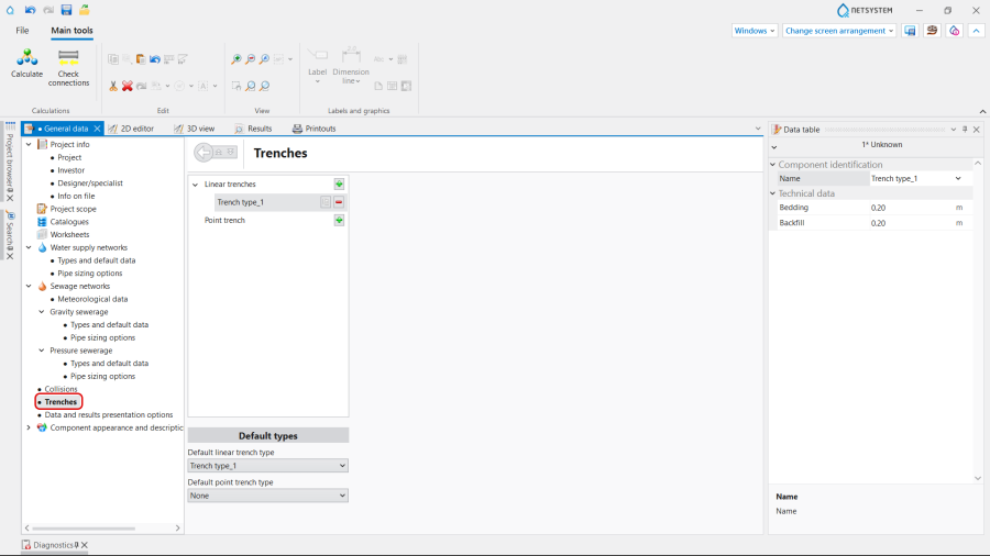
# (Optionally) ''<IS_TS id=Wykopy/>'' - add ''<IS_TS id=DomyslnyTypWykopuLiniowego/>'' and ''<IS_TS id=DomyslnyTypWykopuPunktowego/>''. <br/>[[File:Designing water supply network Trenches.png|900 px|left|thumb|5. <IS_TS id=Wykopy/>.]]<br clear="all"/><br/>
# (Optionally) ''<IS_TS id=Wykopy/>'' - add ''<IS_TS id=DomyslnyTypWykopuLiniowego/>'' and ''<IS_TS id=DomyslnyTypWykopuPunktowego/>''. <br/>[[File:Designing water supply network Trenches.png|900 px|left|thumb|5. <IS_TS id=Wykopy/>.]]<br clear="all"/><br/>
===Importing geodetic map===
===Import mapy geodezyjnej===
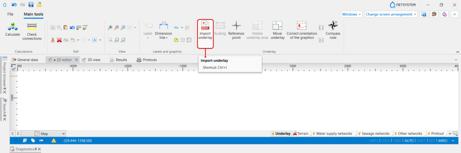
Use ''<IS_TS id=btImportujPodkladZPlikuDXF/>'' function to download the geodetic map in compatible underlay file formats:
Use ''<IS_TS id=btImportujPodkladZPlikuDXF/>'' function to download the geodetic map in compatible underlay file formats:
# Wybrać zakres edycji ''<IS_TS id=PH_NS5_SAN_T/>''.
# Insert basic elements:
# Wstawić podstawowe elementy:
#* ''<IS_TS id=iNamePrfStudzienkaWod/>'',
#* ''<IS_TS id=iNamePrfStudzienkaWod/>'',
#* ''<IS_TS id=iNamePrfSkrzyzowanieSieciWod/>'',
#* ''<IS_TS id=iNamePrfSkrzyzowanieSieciWod/>'',
#* ''<IS_TS id=iNamePrfHydrant/>'',
#* ''<IS_TS id=iNamePrfHydrant/>'',
#* ''<IS_TS id=iNamePrfWejscieDoBudWod/>'';
#* ''<IS_TS id=iNamePrfWejscieDoBudWod/>'';
# Connect network elements using ''<IS_TS id=iNamePrfOdcinekSieciWod/>''. <br/>'''''Note:''''' Alternatively, the network can be drawn first, and then the basic elements can be positioned.
# Połączyć elementy używając ''<IS_TS id=iNamePrfOdcinekSieciWod/>''. <br/>'''''Uwaga:''''' Alternatively, the network can be drawn first, and then the basic elements can be positioned.
# Wstawić element ''<IS_TS id=NetZasuwa/>''.<br/>[[File:Designing water supply network WSN elements.png |900 px|left|thumb|10. <IS_TS id=PH_NS5_SAN_T/> elements.]]<br clear="all"/><br/>
===Editing data of network elements===
===Edycja danych elementów sieci===
# In the ''<IS_TS id=DataEditorTable/>'' window determine required data for the network elements:
# W oknie ''<IS_TS id=DataEditorTable/>'' określić wymagane dane dla elementów sieci:
#* ''<IS_TS id=strPoleTerenProj/>''. The ''<IS_TS id=strAUTOModeName/>'' mode sets the following parameters:
#* ''<IS_TS id=strPoleTerenProj/>''. The ''<IS_TS id=strAUTOModeName/>'' mode sets the following parameters:
#** for the ''<IS_TS id=iNamePrfStudzienkaWod/>'' / ''<IS_TS id=iNamePrfSkrzyzowanieSieciWod/>'' within the ''<IS_TS id=ScopeNet_terrain/>'' ''<IS_TS id=stringProjektowane/>'' area, the value of ''<IS_TS id=strPoleTerenProj/>'' is taken from the model of ''<IS_TS id=ScopeNet_terrain/>'',
#** for the ''<IS_TS id=iNamePrfStudzienkaWod/>'' / ''<IS_TS id=iNamePrfSkrzyzowanieSieciWod/>'' within the ''<IS_TS id=ScopeNet_terrain/>'' ''<IS_TS id=stringProjektowane/>'' area, the value of ''<IS_TS id=strPoleTerenProj/>'' is taken from the model of ''<IS_TS id=ScopeNet_terrain/>'',
The project contains complete default data configured in the template file.
Kroki do wykonania
Otwarcie nowego pliku projektu
Uruchomić NetSystem 5.5. Uwaga: The program interface and basic functions are very similar to those used in InstalSystem 5.5. Therefore, below are links to articles related to InstalSystem 5.5 that are also applicable to NetSystem 5.5.
Choose the required template file (optional). Więcej informacji na ten temat:Template files.
Edycja katalogów i danych ogólnych projektu
Fill in the default data in the Dane ogólne window:
Katalogi produktów – select and move necessary catalogues to the Katalogi w projekcie: table. To speed up the selection, the filters can be used. Więcej informacji na ten temat:Using catalogues and catalogues data in the project. 1. Katalogi produktów.
Arkusze robocze / Arkusze map:
(Optionally) Modify The Domyślna rzędna terenu,
Add new Arkusze map, if necessary;
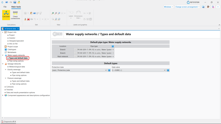
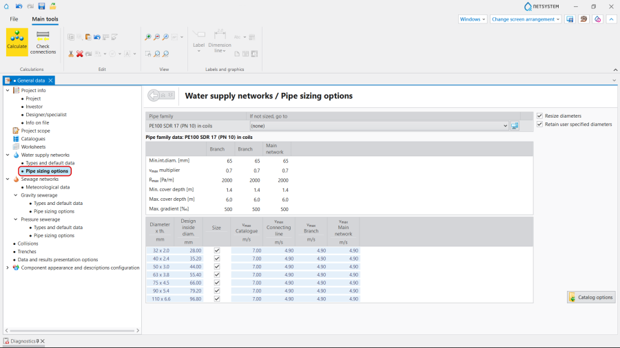
Sieci wodociągowe / Typy i dane domyślne - append:
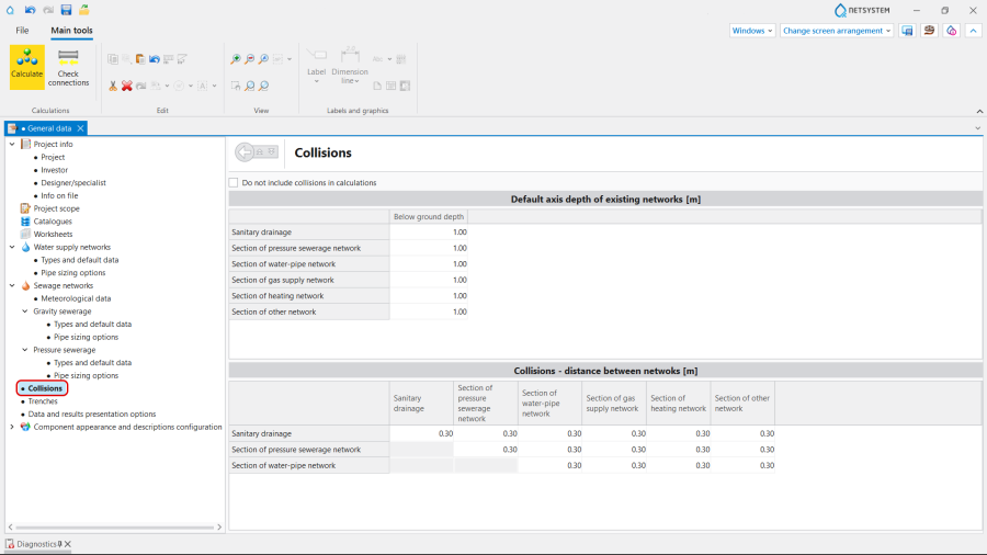
Kolizje - check and adjust, if necessary, the settings for conflicting networks relating to the Domyślne zagłębienie sieci istniejących and Kolizje - odległości mijania sieci. 4. Kolizje.
(Optionally) Wykopy - add Domyślny typ wykopu liniowego and Domyślny typ wykopu punktowego. 5. Wykopy.
Import mapy geodezyjnej
Use Importuj podkład function to download the geodetic map in compatible underlay file formats:
DWG
DXF
PDF
BMP
PNG
JPG
GIF
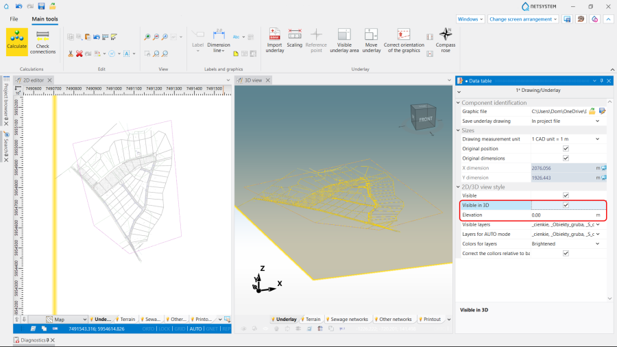
ASC 6. Importuj podkład. For DWG Rysunek/Podkład the setting Widoczny w 3D can be turned on and the Rzędna at which the map should be visible can be specified in the Tabela danych window . 7. Widoczny w 3D. Więcej informacji na ten temat:Import underlay files.
Modelowanie terenu
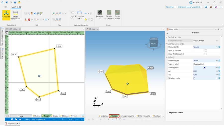
Related functions are available when the Teren editing scope is active:
8. Modelowanie terenu.
Modelowanie terenu:
Insert TerenProjektowane element or
Insert TerenIstniejące element;
Punkt terenu:
Insert Punkt terenu - Projektowany elements or
Insert Punkt terenu - Istniejący elements;
Jezdnia:
Insert Jezdnia - Projektowana element or
Insert Jezdnia - Istniejąca element. 9. TerenProjektowane.
Edycja sieci
Carry out inserting and graphic editing operations using the AUTO mode.
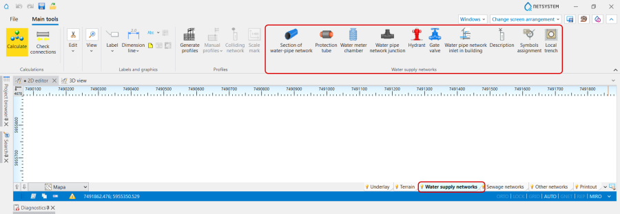
Wybrać zakres edycji Sieci wodociągowe.
Wstawić podstawowe elementy:
Studzienka wodomierzowa,
Węzeł sieci wodociągowej,
Hydrant,
Wejście sieci wod. do budynku;
Połączyć elementy używając Odcinek sieci wodociągowej. Uwaga: Alternatively, the network can be drawn first, and then the basic elements can be positioned.
Wstawić element Zasuwa. 10. Sieci wodociągowe elements.
Edycja danych elementów sieci
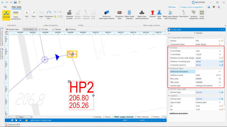
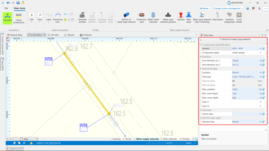
W oknie Tabela danych określić wymagane dane dla elementów sieci:
Rzędna terenu projektowanego. The AUTO mode sets the following parameters:
for the Studzienka wodomierzowa / Węzeł sieci wodociągowej within the TerenProjektowane area, the value of Rzędna terenu projektowanego is taken from the model of Teren,
for the Studzienka wodomierzowa / Węzeł sieci wodociągowej outside the TerenProjektowane area, the Domyślna rzędna terenu for the Mapa is propagated by default;
Rzędna terenu istniejącego. The AUTO mode sets the following parameters:
for the Studzienka wodomierzowa / Węzeł sieci wodociągowej within the TerenIstniejące area, the value of Rzędna terenu istniejącego is taken from the model of Teren,
for the Studzienka wodomierzowa / Węzeł sieci wodociągowej outside the TerenIstniejące area, the Domyślna rzędna terenu for this element is taken from the Rzędna terenu projektowanego;
Rzędna wejścia do budynku - for the Wejście sieci wod. do budynku,
Funkcja - for the Węzeł sieci wodociągowej,
Wypływ w punkcie, Wym. ciśn. and Ciśn. max. - for the Wejście sieci wod. do budynku and Hydrant,
Rodzaj wejścia do bud - for the Wejście sieci wod. do budynku,
Kształt and Dimensions- for the Studzienka wodomierzowa. 11. Editing data of network elements.
(Optionally) Modify network elements data if data differs from the default settings; 12. Tabela danych.
(Optionally) Modify Wykopy data if data differs from the default settings;
(Optionally) Insert Rura ochronna;
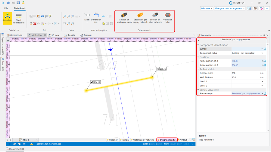
(Optionally) Open Pozostałe sieci working scope. Insert uncalculated conflicting Inne sieci, defining the Stan elementu, Położenie and Dane techniczne. 13. Pozostałe sieci.
Network structure correctness verification
Verify correctness of the network structure using Sprawdź połączenia function (shortcut: Shift + F2);
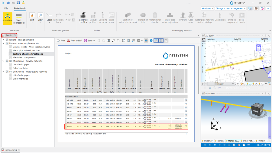
Verify the results in the Wyniki tables; 15. Wyniki tables.
Every item of the network presented in the Wyniki tables can be found in active windows by using icon.
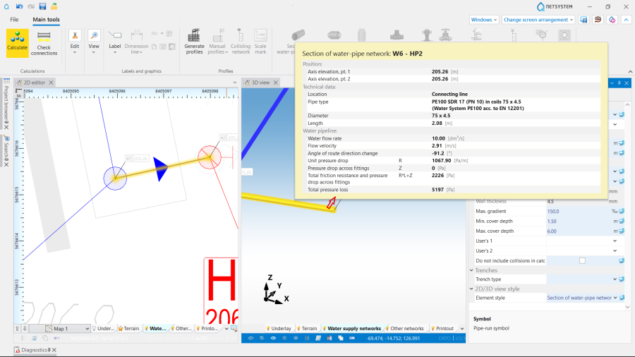
The data of each element can be verified directly in the drawings by means of component labeling and hints containing tables with basic parameters. 16. Visual verification in the Widok 3D window.
Preparing drawings and results for printing / exporting
To have the results for Sieci wodociągowe elements included in the printout of a drawing, appropriate labels must be inserted. Więcej informacji na ten temat:Preparation of drawings for export / printing.








 in the Obliczenia section of the toolbar;

 icon.
icon.