Projektowanie instalacji wentylacji mechanicznej: Różnice pomiędzy wersjami
(Utworzono nową stronę "{{Article table |commercial_product1=InstalSystem 5 |p2 =<!--gdy jest kolejny produkt handlowy, zamienić na->"produkt_handlowy2="--> |p3...") |
(tlumaczenie akapitów od poczatku do edycji danych ogolnych) |
||
| Linia 16: | Linia 16: | ||
}} | }} | ||
== | ==Zakres lekcji== | ||
Artykuł prezentuje podstawową ścieżkę pojrktowania ''<IS_TS id=InstalacjeWentylacyjne/>'' dla budynku mieszkalnego na bazie gotowych komponentów. | |||
== | ==Potrzebne moduły i konfiguracja programów== | ||
'''InstalSystem 5''' | '''InstalSystem 5''' zawierający moduł: | ||
*'''''<IS_TS id=PH_IS5_VENT/>'''''. | *'''''<IS_TS id=PH_IS5_VENT/>'''''. | ||
== | ==Plik projektu== | ||
Plik projektu wykorzystywany w tej lekcji: [[Mechanical ventilation installation in residential building (example for the lesson)]]. | |||
== | ==IStan początkowy= | ||
Projekt zawiera kompletne dane domyślne skonfigurowane w pliku szablonu. Struktura budynku została opracowana na podstawie podkładów DWG. | |||
=== | |||
==Kroki do wykonania== | |||
===Otwarcie pliku ze stanem początkowym=== | |||
# Podczas tworzenia nowego projektu należy wybrać z listy szablon zawierający domyślne dane systemu wentylacji lub, | |||
# Wczytać plik projektu zawierający strukturę budynku budynku - minimalna zawartość to prawidłowe rzędne, grubości stropów i ręcznie utworzone ''<IS_TS id=iNameKonstrPomieszczeniePlural/>''. | |||
===Edycja danych ogólnych porjektu=== | |||
Fill in the default data in the ''<IS_TS id=btProjectOptions/>'' window: | Fill in the default data in the ''<IS_TS id=btProjectOptions/>'' window: | ||
# ''<IS_TS id=ZakresProjektu/>'' - determine project scope: ''<IS_TS id=InstalacjeWentylacyjne/>''.<br/>[[File:Project scope vent.png|900 px|left|thumb|1. <IS_TS id=ZakresProjektu/>.]]<br clear="all"/> | # ''<IS_TS id=ZakresProjektu/>'' - determine project scope: ''<IS_TS id=InstalacjeWentylacyjne/>''.<br/>[[File:Project scope vent.png|900 px|left|thumb|1. <IS_TS id=ZakresProjektu/>.]]<br clear="all"/> | ||
Wersja z 17:44, 28 sie 2024
| Produkt | InstalSystem 5 |
| Typ artykułu | LEKCJA PROJEKTOWANIA |
| Ostatnia aktualizacja | 2024-07-29 |
Zakres lekcji
Artykuł prezentuje podstawową ścieżkę pojrktowania Instalacje wentylacyjne dla budynku mieszkalnego na bazie gotowych komponentów.
Potrzebne moduły i konfiguracja programów
InstalSystem 5 zawierający moduł:
- .
Plik projektu
Plik projektu wykorzystywany w tej lekcji: Mechanical ventilation installation in residential building (example for the lesson).
=IStan początkowy
Projekt zawiera kompletne dane domyślne skonfigurowane w pliku szablonu. Struktura budynku została opracowana na podstawie podkładów DWG.
Kroki do wykonania
Otwarcie pliku ze stanem początkowym
- Podczas tworzenia nowego projektu należy wybrać z listy szablon zawierający domyślne dane systemu wentylacji lub,
- Wczytać plik projektu zawierający strukturę budynku budynku - minimalna zawartość to prawidłowe rzędne, grubości stropów i ręcznie utworzone Pomieszczenia.
Edycja danych ogólnych porjektu
Fill in the default data in the Dane ogólne window:
- Zakres projektu - determine project scope: Instalacje wentylacyjne.

1. Zakres projektu. - Katalogi produktów – select and move necessary catalogues to the Katalogi w projekcie: table. To speed up the selection, the filters can be used. Więcej informacji na ten temat: Using catalogues and catalogues data in the project.
- General data editing:
- Zarządzanie kondygnacjami:
- Create the appropriate number of Kondygnacje / sub-levels (by interpreting from IFC or manually);
- Set storey data:
- ΔHwent,g - Domyślna odległość osi kanału sztywnego od górnego stropu;
- ΔHwent,flex,g - Domyślna odległość osi kanału elastycznego od górnego stropu;
- ΔHwent,naw,śc - Domyślna odległość nawiewnika ściennego od sufitu podwieszanego;
- ΔHwent,wyw,śc - Domyślna odległość wywiewnika ściennego od sufitu podwieszanego;
- ΔHwent,naw,suf,g - Domyślna odległość nawiewnika sufitowego od sufitu podwieszanego;
- ΔHwent,wyw,suf,g - Domyślna odległość wywiewnika sufitowego od sufitu podwieszanego;
- ΔHwent,naw,podł - Domyślna odległość nawiewnika podłogowego od podłogi;
- ΔHwent,wyw,podł - Domyślna odległość wywiewnika podłogowego od podłogi.
- (Optionally) Dane pomieszczeń - for each/selected Typ pomieszczenia, used in the project, set the values of:
- Strumień objętości powietrza usuwanego (V̇ex), Strumień objętości powietrza dostarczanego (V̇su) or Minimalna krotność wymian powietrza went. (nmin);
- Zarządzanie kondygnacjami:


- Instalacje wentylacyjne / Typy i dane domyślne – append default types:
- Domyślne typy rur i izolacji: Kanał sztywny;
- Domyślne typy rur i izolacji: Kanał elastyczny;
- Typy domyślne: Inne elementy:
- Centrala wentylacyjna / Rekuperator,
- Rozdzielacz wentylacyjny nawiewny / Rozdzielacz wentylacyjny wywiewny,
- Nawiewnik ścienny / Wywiewnik ścienny, Nawiewnik sufitowy / Wywiewnik sufitowy, Nawiewnik podłogowy / Wywiewnik podłogowy;
- Sprawność odzysku ciepła: Zgodnie z danymi katalogowymi, Zgodnie z danymi dla strat ciepła or Narzucone;
- (Optionally) control and adjustment of the default value of vmax, m/s in the specified locations of the installation.
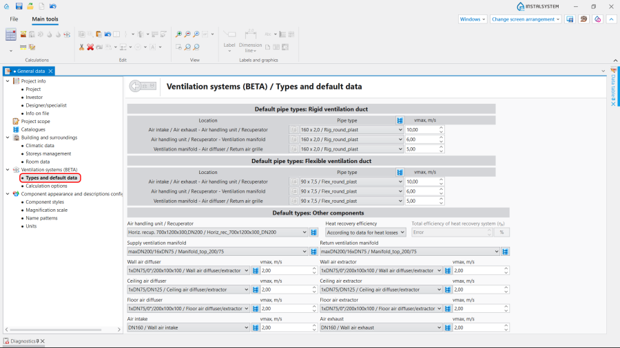
3. Typy i dane domyślne.
- Instalacje wentylacyjne / Opcje obliczeń:
- Select the Sposób wyznaczania ilości powietrza wentylacyjnego;
- (Optionally) enable the function Sprawdzaj minimalną ilość powietrza wentylacyjnego na mieszkańca;
- (Optionally) improve the value of θe - Projektowa temperatura zewnętrzna taken by the Czerpnia unit.

4. Opcje obliczeń.
- Instalacje wentylacyjne / Typy i dane domyślne – append default types:


Editing on the drawings
Editing the data
Set or modify the values of Strumień objętości powietrza usuwanego (V̇ex), Strumień objętości powietrza dostarczanego (V̇su) or Minimalna krotność wymian powietrza went. (nmin) for each particular Pomieszczenie in the Tabela danych in the Konstrukcja project scope.

Editing the installation
Carry out inserting and graphic editing operations using the AUTO and ORTO modes.
- Select editing scope Wentylacja.
- Insert Wentylacja elements:
- Rekuperator,
- Rozdzielacz (nawiew) and Rozdzielacz (wywiew);

6. Insert Rekuperator and Rozdzielacz (nawiew).
- Insert Wentylacja terminals and indicate the Kąt obrotu, if necessary:
- Czerpnia,
- Wyrzutnia,
- Nawiewnik (kratka, anemostat nawiewny) powietrza świeżego,
- Wywiewnik (kratka, anemostat wywiewny) powietrza zużytego;

7. Insert Wentylacja terminals and indicate the Kąt obrotu.
- Insert Pion kanałów went.;
- Connect installation elements using Kanał sztywny or Kanał elastyczny.


Editing the element data
In the case of necessity modify the Wentylacja elements data in the Tabela danych window, in particular:
- Typ of the Wentylacja terminal;
- V̇su / V̇ex for the Wentylacja terminal;
- Odległość od stropu / Rzędna for the Rekuperator;
- Odległość od stropu / Rzędna for the Rozdzielacz (nawiew) and Rozdzielacz (wywiew);
- Odległość od stropu / Rzędna for the Kanały wentylacyjne;
- Typ rury for the Kanały wentylacyjne.
Verifying the correctness of the installation structure.
- Verify the correctness of the connections of the installation components using the Sprawdź połączenia function (Shortcut: Shift + F2);
- Verify the correctness of the installation structure using the Widok 3D;
- Adjust the layout of the Kanały wentylacyjne according to external factors, e.g. passages through walls, overlaps with other installations.
Running the calculations
- Start the calculation of the Instalacje wentylacyjne by clicking
 in the Obliczenia section of the toolbar;
 - Сheck messages the Diagnostyka window;
- In the case of necessity verify and adjust the installation, for example:
- increase the Średnice / Wymiary of the Kanały wentylacyjne, if Przekroczona maksymalna prędkość przepływu powietrza (%s m/s > %s m/s) in the duct;
- increase Wymiary of the Nawiewnik / Air extractor or add more Kanały wentylacyjne and Nawiewnik / Air extractor, if Przekroczona maksymalna prędkość przepływu powietrza (%s m/s > %s m/s) in the Wentylacja terminal;
- correct the values of V̇su and V̇ex, in the case of Niezrównoważony bilans powietrza wentylacyjnego (ΣV̇su=%s m3/h, ΣV̇ex=%s m3/h).
Verification of results
- After calculations, the system layout should be verified visually by means of the Widok 3D;
- If the calculations end with at least one error, the layout may be unreliable;
- The data of each Wentylacja element can be verified directly in the drawings.

8. Visual verification in the Widok 3D window. - Other forms of presentation of calculation results are: component labels and tables of results Więcej informacji na ten temat: Presentation of the calculations result.

9. Wyniki - wentylacja.


=Przygotowanie rysunków do wydruku/eksportu
- To have the results for Wentylacja installation elements included in the printout of a drawing, appropriate labels must be inserted Więcej informacji na ten temat: Preparation of drawings for export / printing.
- Completed drawings can be printed and/or exported Więcej informacji na ten temat: Export / print results and drawings.